The project
Costec Systems supplied a high-fidelity, site-specific simulation of the energy plant to a large Australian steel mill. Delivered to the mill as a stand-alone simulation, it was used as a tool to investigate a variety of aspects of the plant's dynamic behaviour under both normal and upset conditions. The principal objectives were to achieve (a) a better understanding of the dynamic behaviour and distribution of gases and steam throughout the site and (b) better performance of the various modulating control loops. A third and later objective was the technical evaluation of the introduction of natural gas as a supplementary fuel source, to be mixed with the two on-site sources – coke oven and blast furnace gases. As part of a site and environment safety assessment the simulation was also used to quantify the rate and volume of gas release in the event of a major gas pipe rupture and to identify appropriate control measures.
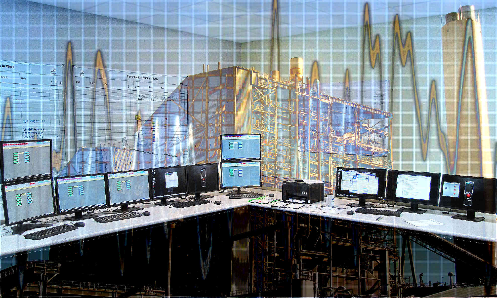
The simulation software, including its Simulation Management System, runs on a standard high performance PC under the Windows operating system, with multiple display screens. Several interactive display tableaux give the user access to control devices and measurements, as in a normal control room.
The plant
The plant included 2 blast furnaces, multiple coke oven batteries, 5 gas-fired boilers (with dual gas firing), 3 differing pressure levels, several steam turbine drives, 2 large gas holders (one for each gas type), together with connecting ducts and pipes, distributed over a site of some 8 km2. Connecting pipes and ducts are up to 900m long and up to 2m diameter, with several regulating and shutoff valves. The simulation modelling took this large spatial extension into account in its treatment of the dynamic behaviour of gas flows and masses. The coke oven gas (COG), blast furnace gas (BFG) and utility steam networks, together with air supplies to the blast furnaces (turbine-driven blowers) and boilers (electrically-driven fans), were simulated dynamically in real and accelerated time and integrated into a single simulation unit, complete with connections to steam and gas consumers (plate and rolling mills, sintering plant, basic oxygen plant and other processes found in a typical steelworks of this size), together with their associated measurements and control loops.
Operations
A steelworks is a large and very interactive connection of numerous gas and steam producers and consumers, operating largely independently of each other. These independent but interrelated operations produce a variety of differing underlying cyclic demands for the production and consumption of gases and steam. It was desirable to schedule realistic variations of these quantities within the simulation to reproduce typical operations of the plant. For this purpose Costec Systems applied advanced data analysis methods to actual operating records to identify the underlying process cycles, both frequency and intensity, and to relate them to their sources. This information was used to reproduce the plant’s cyclic behaviour in the simulation by scheduling the behaviour of the various producers and consumers and was of significant value in guiding improvements to control system behaviour.
Simulation modelling of the COG and BFG systems ensured that the net mass balance of gas within the piping network was maintained by appropriate variation of the mass of gas in the respective gas holders. The simulation reproduced the regulating action of the gas holder control valves and gas bleed valves to maintain pressure throughout each network. The dynamic simulation of the movement of the gasholder pistons set limits on their rate of travel as required to protect the seals. Pressure control valves controlled the distribution of pressures and flows throughout each network.
Each boiler simulation realistically reproduced the relationship between fuel flow (of each gas type) and steam production and interacted realistically with the balance of the steam network and consumers, as these followed the plant’s basic cycles. The fuel supply control system for each boiler reflected the mode of operation of the actual plant’s boilers to control steam pressures individually and in the common headers. Letdown control valves maintained setpoint pressures in the lower pressure networks.
Delivery time
The complete simulation was developed and delivered within three months of order.
Case Study 1. A Dynamic Simulation of the Energy Plant at a Large Steelworks
Case Study 2. A Cogeneration Plant Financial Assessment
Case Study 3. A Process Plant Operations Analysis
Case Study 4. A Dynamic Analysis of Steam Utilities in an Oil Refinery